

Central Air Conditioning Control Signal Connection Cable
Central Air Conditioning Control Signal Connection Cable Description Central Air Conditioning Control Signal Connection Cable Description Central Air Conditioning Control Signal Connection Cable Description Here is an expanded overview of central air conditioning control signal connection…
Product Introduction
Central Air Conditioning Control Signal Connection Cable Description
|
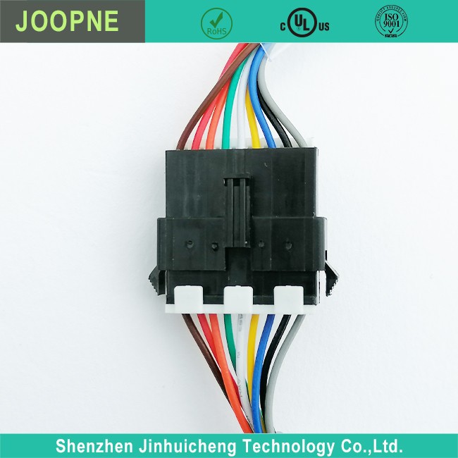
· Molded |
|
· Different Fuction cable as Requirement |
|
· Suitable for Central Air Conditioner use |
|
· UL listed for safety; IEC standard; TUV |
Central Air Conditioning Control Signal Connection Cable Description
|
Rated Voltage: |
10V-24V |
|
Rated Current: |
1A-5A |
|
Connector: |
Molded |
|
Power Supply: |
Electric |
Central Air Conditioning Control Signal Connection Cable Description
Here is an expanded overview of central air conditioning control signal connection cables:
The control signal cable connects the thermostat to the air conditioner’s control board. Its main function is to send a low voltage signal from the thermostat to turn the air conditioner on and off. It does not carry the high voltage/current needed to power the air conditioner’s compressor or condenser fan motor.
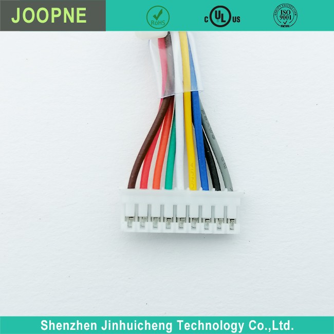
The cable typically consists of 2 or 3 wires:
1. Common wire – This connects to the C or COM terminal on the control board. It provides the return path for the control signal.
2. Signal wire – This connects to the Y or Y1 terminal and carries the 24V AC or DC signal from the thermostat. When the thermostat calls for cooling, it sends voltage through this wire to turn on the air conditioner.
3. (Optional) Auxiliary wire – Some systems have a 3rd wire that connects to the G or AUX terminal. This is used for a fan relay or auxiliary heat.
The wire gauge is usually between 18 and 22 AWG since only a low voltage control signal is being sent. Larger wire is not needed.
The cable connects from the thermostat terminals (R, G, Y, C) to the corresponding terminals (R, G, Y, C) on the air conditioner’s control board inside the unit.
It is critical to correctly match the wire colors when connecting. Reversing the common and signal wires can damage the control board. So take care to connect:
– Common wire to C or COM terminals
– Signal wire to Y or Y1 terminals
– Auxiliary wire (if present) to G or AUX terminals
By understanding these basics of the control signal cable, you can properly and safely connect your thermostat to your central air conditioner.


Frequently Asked Questions
Central Air Conditioning Control Signal Connection Cable
What gauge wire should I use for the cable?
+
–
Typically 18 to 22 gauge wire is sufficient since only a low voltage control signal is being sent. Larger wire gauges are not needed.
How many wires do I need?
+
–
Most systems use 2 or 3 wires: Common wire Signal wire Optional auxiliary wire for a fan relay or auxiliary heat
Can I use regular electrical cable for the control signal cable?
+
–
Yes, standard electrical cable with stranded copper conductors is fine. Just make sure the gauge is between 18 and 22 AWG.
Do I need to shield the cable?
+
–
In most cases, no. A standard unshielded cable will work fine for carrying the low voltage control signal. Shielding is typically not needed.
What terminals do the wires connect to on the air conditioner control board?
+
–
The wires connect to the following terminals: Common wire connects to C or COM terminal Signal wire connects to Y or Y1 terminal Auxiliary wire (if present) connects to G or AUX terminal
Hot Tags: central air conditioning control signal connection cable, China central air conditioning control signal connection cable manufacturers, suppliers, factory, self booster cables, lcd lvds cable, Molex Cable Assembly, ffc usb, car battery red and black cable, cable driven robotic arm


Send Inquiry